
Engineered for high-dynamic cycling, zero-noise sinking, and seamless grid energy recovery in mission-critical R&D facilities.
An authoritative technical analysis on regenerative energy dissipation, grid compliance, and battery emulation topologies for New England's leading technology hubs.
The Greater Boston area—encompassing Cambridge's Kendall Square, the Route 128 tech belt, and the Route 495 industrial technology corridor—has evolved into the global epicenter for autonomous systems, robotic automation, advanced clean energy tech, defense innovation, and medical bio-engineering.
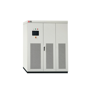
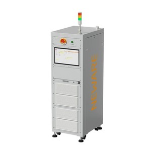
Engineering teams in Boston-area tech firms require advanced power electronics testing infrastructure. Standard resistive electronic loads convert high-power discharge test energy directly into ambient thermal heat, placing massive cooling loads on urban HVAC systems and wasting valuable electrical energy. Regenerative electronic loads solve this operational bottleneck by recovering over 96% of absorbed DC power and feeding clean, low-THD AC power back into the local facility grid.
Traditional programmable electronic loads rely on conventional voltage-fed bridge topologies with large parallel output capacitor banks. When testing fast transient power devices such as Silicon Carbide (SiC) or Gallium Nitride (GaN) traction inverters, high internal capacitance creates severe instantaneous surge currents during voltage steps.
Our direct USA-engineered manufacturing methodology utilizes a robust current-fed power topology. An energy-storing inductor is placed directly on the primary DC link. This fundamental architecture delivers distinct physics-level benefits:
Technical evaluation metrics comparing industrial regenerative electronic loads against legacy resistive load systems.
| Technical Parameter | Traditional Resistive Load | Standard Regenerative Load | Our USA-Factory Regenerative System |
|---|---|---|---|
| Energy Thermal Efficiency | 0% (100% Dissipated as Waste Heat) | 85% - 90% Grid Recovery | > 96% Active Grid Energy Recovery |
| Grid THD (Total Harmonic Distortion) | N/A (Non-Regenerative) | < 5% at Full Load | < 3% Clean Sinusoidal Grid Injection |
| Transient Response Slew Rate | Slow (Thermal Lag Dependent) | 2 ms - 5 ms Rise Time | < 1 ms Dynamic Response (SiC Optimized) |
| DC Bus Topology | High-Capacitance Voltage-Fed | Standard Switching Bridge | Rugged Current-Fed Inductive DC Link |
| Isolation & Protection | Basic Fuse Protection | Galvanic Isolation Transformer | Isolated Digital Gate Drives & Over-Voltage Trip |
| Parallel Scalability | Complex Analog Load Sharing | Master/Slave Configuration | MagnaLINK™ Distributed DSP (up to 10 MW) |
Tailored power testing solutions built to satisfy the precise engineering demands of local institutions, defense prime contractors, and biotechnology laboratories.
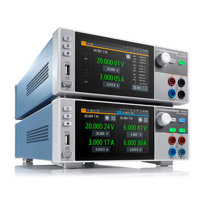
Autonomous mobile robots (AMRs) and legged robotic systems experience continuous high-peak regenerative braking cycles. Our high-dynamic battery simulators mimic real-world lithium pack internal resistance variations, allowing robotics developers to validate motor drive regeneration efficiency without degrading physical battery packs.
For clean energy startups focused on grid-tied solar inverters, flow batteries, and green hydrogen electrolyzers, our regenerative loads function as dual-quadrant grid simulators. They enforce IEEE 1547 and UL 1741 compliance testing by simulating grid voltage sags, frequency fluctuations, and reverse power flow.
Defense primes building pulsed radar power arrays, electromagnetic launch equipment, and unmanned subsea vehicle propulsion require rugged current-fed power systems that tolerate severe dynamic step loads, severe micro-arcing, and high ambient vibration conditions.
Biomedical micro-power developers utilizing coin cell battery simulators (CR2032/CR2016) achieve sub-microamp noise isolation to accurately benchmark implantable sensors, wireless surgical tools, and wearable continuous glucose monitors under dynamic telemetry drain profiles.
The regulatory and commercial environment for industrial power electronics in Massachusetts is rapidly tightening under modern sustainability initiatives and grid interconnection directives:
The Massachusetts Clean Energy Center (MassCEC) has established aggressive net-zero emissions targets for commercial research space. Facilities operating large-scale energy storage test benches are incentivized to implement regenerative heat-mitigating test infrastructure to retain building energy certifications.
Local utility distribution networks operated by Eversource and National Grid strictly monitor harmonic injection limits. Our regenerative factory loads utilize active power factor correction (PFC > 0.99) and low harmonic distortion active front ends to guarantee seamless utility interconnection approval.
With Boston's Building Energy Reporting and Disclosure Ordinance (BERDO 2.0), commercial lab buildings face severe financial penalties for high carbon emissions. Regenerative loads directly lower facility energy consumption, directly aiding property managers in achieving BERDO compliance.
Direct vertical integration delivers complete hardware control, predictable lead times, and uncompromised build quality.
Every magnetics assembly, sheet-metal enclosure, planar transformer winding, and high-voltage circuit board is engineered and manufactured inside our domestic facility. Engineering sits directly alongside production, eliminating overseas supply chain bottlenecks.
While traditional overseas instrumentation importers routinely quote 20 to 36-week delivery delays for customized megawatt-scale power systems, our domestic factory streamlined production flow yields consistent 4-to-6-week build schedules for fully custom power configurations.
100% of manufactured units undergo rigorous full-load thermal and electrical burn-in testing prior to shipment. Every system ships with complete factory calibration certificates traceable to NIST standards.
Detailed technical answers for facility managers, chief power architects, and test engineering directors.
Our regenerative loads utilize an active front-end (AFE) inverter stage that synchronizes automatically with local three-phase building power (208V, 480V, or 600V AC at 60 Hz). The system converts absorbed DC energy into low-distortion AC current that flows directly back into your facility's internal electrical distribution panel, offsetting real-time electricity pulled from Eversource or National Grid lines.
With our low-latency digital signal processing (DSP) platform and current-fed switching topology, our systems achieve sub-millisecond dynamic step response times (<1 ms). This speed is critical for simulating high-frequency inverter ripple, vehicle acceleration transient bursts, and defense radar pulse drain profiles without voltage overshoot.
Yes. Our programmable battery simulators incorporate real-time programmable internal resistance modeling (Rint mode). Engineers can program dynamic state-of-charge (SOC) curves, temperature coefficient offsets, and cell degradation profiles to evaluate BMS active balancing and motor drive fault tolerance under exact real-world battery conditions.
In space-constrained urban facilities (such as multi-story lab buildings in Cambridge or Boston proper), rejecting hundreds of kilowatts of heat into ambient room air requires massive ductwork and high acoustic noise. Our liquid-cooled (ML Series) power units utilize closed-loop liquid cooling plates, transferring heat efficiently to facility chilled water lines and reducing acoustic noise below 60 dBA.
Absolutly. Utilizing our proprietary MagnaLINK™ master-slave digital interface, multiple standard power units can be paralleled seamlessly up to 10 MW total output. The control software automatically balances current sharing across all sub-cabinets, treating the parallel system as a single unified instrument with a shared SCPI command interface.
Standard units come equipped with isolated Ethernet/LXI, USB, RS-232, and isolated 37-pin analog/digital I/O. Optional interfaces include IEEE-488 GPIB and Modbus TCP. We provide native National Instruments LabVIEW drivers, IVI-COM/IVI-C drivers, and full Python integration documentation for seamless automated test equipment (ATE) integration.
Discuss your exact voltage envelope, peak current dynamic profile, and local facility integration requirements directly with our technical engineering team.
Contact Us