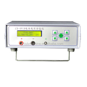
Lithium Ion Battery Voltage Current Capacity Tester
Application: Cell Cycling & QA Screening
Precision: ±0.05% FS Voltage/Current
Features: Automated Data Logging

Explore our high-performance DC power sources, coin-cell emulators, bi-directional simulators, and BMS validation hardware tailored for Austrian R&D labs and industrial production facilities.
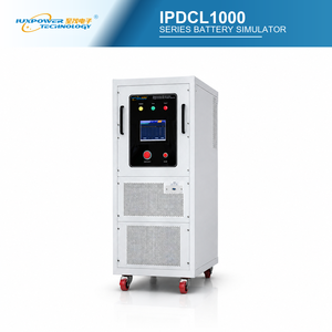
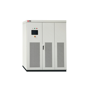
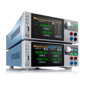
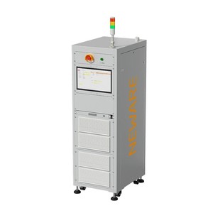
A technical examination of energy storage mechanisms, transient tolerance, dynamic response, and thermal robustness for Austrian engineering teams evaluating high-power DC systems.
In standard commercial switch-mode programmable DC power supplies, a voltage-fed topology is typically employed due to lower initial production costs. In a voltage-fed design, a large bank of aluminum electrolytic or film capacitors resides directly across the output DC bus to smooth output ripple voltage. While effective for static resistive loads, this architecture creates inherent vulnerabilities when subjected to modern dynamic loads such as wide-bandgap (SiC/GaN) traction inverters, arc-melting systems, or fast-pulsed battery cycling units.
When an abrupt short-circuit, low-impedance transient, or regenerative kickback occurs at the output terminals of a voltage-fed power supply, the energy stored inside the massive output capacitor bank is immediately dumped into the Device Under Test (DUT) or internal semiconductor switches ($E = \frac{1}{2} C V^2$). This instantaneous current spike can easily exceed thousands of amperes, stressing internal MOSFETs/IGBTs, triggering over-current latches, or damaging delicate DUT traces.
Conversely, our current-fed power processing topology places a high-frequency energy storage inductor downstream of the primary converter stage, serving as the primary DC storage element. Because the inductor inherently resists instantaneous changes in current ($v = L \frac{di}{dt}$), peak fault current is naturally limited by the physical magnetic structure. If a direct short circuit occurs across the output terminals, the current-fed topology naturally limits the rate of current rise, providing inherent short-circuit immunity, eliminating high-energy capacitive discharge arcs, and permitting continuous operation into dead-short conditions without component degradation.
Conventional DC power supplies operate within a fixed rectangular output envelope, delivering maximum power only at one specific voltage and current rating point (e.g., 500V at 100A for a 50kW unit). Operating at 250V limits output power to only 25kW, forcing test engineers in Austria to purchase multiple specialized power supplies to cover varying operating voltages.
By employing advanced microprocessor-controlled current-fed switching stages, our programmable DC supplies provide a wide Constant-Power Operating Envelope. A single unit can deliver full rated power across a continuous operating range (for example, operating from 50% to 100% of maximum voltage while scaling current inversely). This flexibility enables Austrian laboratories to consolidate test benches, reduce equipment footprint, and lower total capital expenditure (CapEx).
| Performance Characteristic | Current-Fed Topology (Our Standard) | Conventional Voltage-Fed Topology |
|---|---|---|
| Primary Energy Storage | High-Frequency Series Inductor (L) | Large Parallel DC Bus Capacitor (C) |
| Short-Circuit & Arc Tolerance | Inherent physical limitation of di/dt | Destructive capacitive energy dump; frequent trips |
| Dynamic Load Transient Immunity | Robust against inductive kickback & dynamic surges | Vulnerable to over-voltage spikes from DUT energy feeds |
| Operating Power Envelope | Wide Constant-Power Curve over V/I range | Derates linearly with voltage reduction (Fixed V/I) |
| Bipolar & Bi-directional Sinking | Smooth integration with linear MOSFET load stages | Requires complex external reverse-diode protection |
| Long-Term Mean Time Between Failures (MTBF) | > 100,000 Hours (Industrial Grade Magnetic Focus) | Limited by electrolytic capacitor thermal drying |
Austria stands as a European powerhouse for automotive engineering, semiconductor manufacturing, and renewable power infrastructure. Here is how our current-fed DC technology integrates into key Austrian industrial hubs.
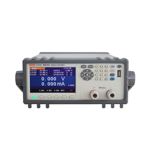
The ACSTYRIA Automotive Cluster around Graz requires rigorous, highly dynamic testing of 800V traction inverters, e-axles, and high-voltage battery modules. Our 150kW to 1MW high-dynamic battery simulators mimic real-world EV pack internal resistance, charge/discharge dynamics, and regenerative braking transients without waveform distortion.
Southern Austria is home to world-leading Silicon Carbide (SiC) and Gallium Nitride (GaN) power semiconductor production. Our SLx and XR series DC power supplies serve as low-ripple, stiff high-voltage DC bus sources for Double Pulse Test (DPT) systems, allowing microelectronics engineers to characterize switching losses up to 1200V safely.
In the industrial heartland of Linz and Upper Austria, heavy decarbonization projects demand megawatt-scale DC power for PEM and alkaline water electrolyzers. Our water-cooled ML Series DC supplies deliver continuous high-current DC power (up to 10 MW via master/slave configuration) with strict harmonic compliance to withstand harsh electrochemical loads.
To support Austria’s goal of 100% renewable electricity by 2030, inverter manufacturers deploy our MagnaDC power supplies paired with PPPE Photovoltaic Power Profile Emulation software. This setup emulates dynamic solar array curves, cloud shadow transients, and temperature sweeps to rigorously validate maximum power point tracking (MPPT) algorithms.
Testing battery management systems for electric trains, commercial buses, and energy storage systems requires multi-channel isolation. Our 24-Channel Battery Cell Simulators allow Austrian test engineers to simulate individual cell voltages, balance currents, SOC drift, and cell fault conditions down to millivolt precision.
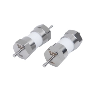
For research institutes like TU Wien, TU Graz, and Silicon Austria Labs (SAL), precision coin-cell simulators (supporting CR2032/2016 formats) provide clean, bipolar low-noise DC power. Researchers can simulate minute battery degradation parameters without investing in oversized bench equipment.
Understanding how evolving DACH regulatory landscapes impact industrial power supply procurement and testing protocols.
Austria’s Erneuerbaren-Ausbau-Gesetz (EAG) mandates an annual addition of 27 TWh of renewable electricity generation by 2030. Achieving this target requires massive deployments of commercial solar inverters, battery energy storage systems (BESS), and bidirectional EV chargers. Equipment connected to the Austrian grid must satisfy stringent grid-interconnection standards, specifically EN 50549-1 / EN 50549-2 and Austrian Power Grid (APG) TOR Erzeuger regulations.
Testing modern grid-tied inverters under these protocols requires high-power programmable DC sources capable of simulating extremely low voltage ride-through (LVRT) events, rapid frequency shifts, and harmonic distortions. Our current-fed MagnaDC supplies feature ultra-fast digital control loops capable of updating setpoints dynamically via SCPI or Modbus TCP, ensuring Austrian OEMs can validate compliance efficiently.
Driven by demands for ultra-fast charging (HPC), Austrian automotive tier-1 suppliers are transitioning from 400V battery architectures to 800V and 1200V bus systems. High voltage testing demands test equipment with high isolation ratings, minimal ground leakage current, and robust safety interlocks. Magna-Power’s programmable supplies offer output voltage ratings spanning from 5V up to 10,000V DC, equipped with high-speed programmable over-voltage (OVP) and over-current (OCP) trip logic to protect high-value prototype powertrains.
Combining four decades of power electronics engineering with rigorous ISO 9001 certified manufacturing control to serve international enterprise accounts.
From sheet metal fabrication and custom magnetic winding (inductors and high-frequency transformers) to surface-mount PCB assembly and full-power burn-in testing, every instrument is manufactured under one roof in Flemington, New Jersey, USA. This eliminates supply chain reliance on third-party sub-assembly vendors.
While many industrial power supply manufacturers impose lead times of 26 to 40 weeks, our standardized modular production model delivers build-to-order configurations (out of 400,000+ potential variations) within 4 to 6 weeks. Critical bench units are also stocked in EU regional logistics centers for fast delivery to Austria.
All instruments shipped to Austria are fully CE Marked, compliant with Low Voltage Directive (LVD) 2014/35/EU and EMC Directive 2014/30/EU. European operations are backed by authorized EU service facilities providing calibration, spare parts, and on-site engineering field support.
Direct technical and logistical answers regarding voltage inputs, customs clearance, software integration, and regional support.
Yes. All high-power MagnaDC and MagnaLOAD systems are built with universal international 3-phase AC input options, specifically supporting 380V, 400V, and 415V AC at 50Hz (3-phase, 3-wire + PE or 4-wire). This allows direct plug-and-play installation in Austrian industrial facilities without needing step-down transformers.
We work with global freight logistics partners (DCH, FedEx, DHL Freight) to deliver under DDP (Delivered Duty Paid) or DAP terms directly to your facility in Vienna, Graz, Linz, Villach, or anywhere in Austria. All shipments include standard EU customs documentation, CE declarations of conformity, and RoHS/REACH compliance paperwork.
Instruments come standard with LXI-compliant Ethernet, USB, and RS-232 interfaces, along with isolated 37-pin analog/digital I/O. Optional IEEE-488 GPIB and Modbus TCP are available. We provide native NI LabVIEW drivers, IVI-COM/IVI-C drivers, and open SCPI documentation for seamless Python, C++, or MATLAB automation.
Absolutely. Current-fed topologies are designed specifically to handle dynamic current steps and reactive loads. The internal inductor smooths current surges, while fast digital signal processors (DSP) maintain steady output regulation even during high slew-rate transitions typical of pulse-width modulated (PWM) inverter loads.
Every product includes a standard 2-Year Factory Warranty covering parts and labor. Factory-traceable calibration certificates are included with every shipped unit. Recalibration and repair support are handled through our dedicated European service hub, minimizing turnaround times.
Air-cooled units suit standard laboratory environments up to ~100kW where room HVAC can handle heat dissipation. For megawatt-scale power systems or cleanroom installations (such as semiconductor fabs in Villach) where room heat load and fan noise must be eliminated, water-cooled units utilizing facility chilled water are recommended.
Need customized voltage/current ratings, dynamic battery emulation profiles, or technical sizing for your test facility in Austria? Contact our technical engineering team today for immediate configuration assistance and formal pricing.
Get a Quote