
Industrial-grade programmable DC equipment engineered for lithium-ion battery testing, BMS validation, and electrochemical laboratory research.
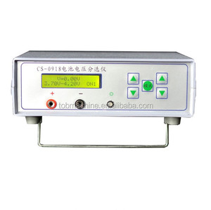
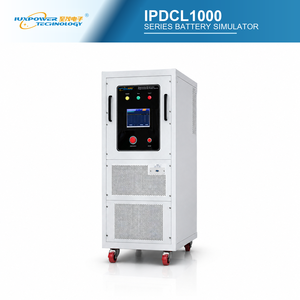
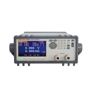
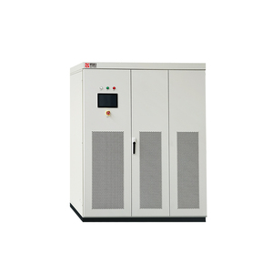
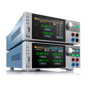
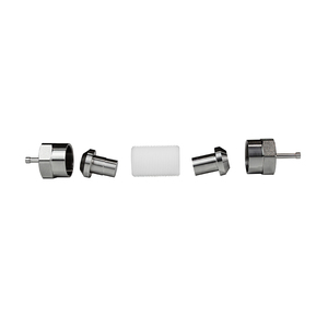
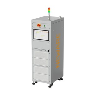
In modern power electronics, the global demand for energy efficiency, electrified mobility, and renewable microgrids has elevated the performance criteria required from high-power DC-DC converters, programmable DC power supplies, and multi-channel battery simulators. As lead OEMs transition toward 800V and 1000V electric vehicle architectures, megawatt-scale energy storage systems (ESS), and wide-bandgap (SiC/GaN) semiconductor devices, test equipment must deliver exceptional transient response times, ultra-low residual ripple, and deterministic bi-directional energy transfer capabilities.
This technical whitepaper examines the core engineering principles governing modern high-precision DC power conversion. It highlights why selecting a trusted manufacturer with vertically integrated production lines—covering everything from planar magnetic coil winding to final full-load environmental burn-in—is critical for mission-critical aerospace, automotive BMS testing, and electrochemical laboratory applications.
Traditional switched-mode power supplies rely heavily on voltage-fed switch topologies, using large capacitive banks across the high-voltage DC link. While cost-effective for standard industrial application profiles, voltage-fed architectures face inherent limitations during rapid load transients, high current surges, and output short-circuits. The rapid discharge of stored capacitive energy during an external fault can lead to destructive switch failure or severe electromagnetic interference (EMI).
Key Engineering Differentiation: Current-fed power topologies utilize a controlled inductor on the primary DC link, storing energy magnetically rather than electrostatically. This inherently suppresses short-circuit current surges, provides immune transient protection, and allows full-power operation across a wide current-voltage operating window.
As illustrated in enterprise-grade DC systems, current-fed topologies yield several key advantages over conventional voltage-fed topologies:
Battery simulators play a pivotal role in validating modern Battery Management Systems (BMS) through Hardware-in-the-Loop (HIL) simulation setups. Unlike a standard programmable DC power supply, a specialized battery simulator must act as a precise, low-impedance two-quadrant or four-quadrant power source/sink capable of modeling real-world chemical cell dynamics.
Modern battery simulator systems achieve dynamic simulation through embedded real-time Digital Signal Processors (DSP) executing state equations for cell behavior:
$$V_{cell}(t, SOC, T) = V_{OCV}(SOC, T) - I_{cell}(t) \cdot R_{internal}(SOC, T) - V_{polarization}(t)$$
Where $V_{OCV}$ represents the open-circuit voltage derived from non-linear State of Charge (SOC) lookup tables, $R_{internal}$ is the programmable internal resistance (emulating battery age and temperature degradation), and $V_{polarization}$ accounts for RC pair electrochemical polarization delays.
Programmable voltage slew rates exceeding 10 V/μs with zero transient overshoot. Ideal for emulating fast pulse discharge curves in cell validation.
Multi-channel simulators feature channel-to-channel and channel-to-ground isolation exceeding 1000V DC, protecting low-voltage BMS microcontrollers.
Bipolar linear MOSFET output stages achieve low output noise (<500 μV RMS), essential for high-precision electrochemical impedance spectroscopy (EIS).
Selecting the appropriate DC conversion architecture depends directly on power density, dynamic response speed, and heat dissipation requirements. The table below compares primary topologies utilized across our factory production lines:
| Topology Family | Power Range | Dynamic Response | Cooling Method | Primary Application Target |
|---|---|---|---|---|
| Current-Fed Switch-Mode (MagnaDC Class) | 1.5 kW – 10 MW | 1 ms – 10 ms | Force Air / Liquid Cold Plate | Industrial DC bus, high-power magnet drives, wind tunnels |
| Linear MOSFET Bipolar (MagnaLOAD / R&S Class) | 100 W – 20 kW | < 10 μs | Precision Forced Air | Electrochemical cell simulation, ultra-low noise lab testing |
| Isolated Multi-Channel Cell Simulator | 1 W – 50 W / ch (24+ ch) | < 50 μs | Internal Convection / Fan | BMS HIL board-level validation, fault injection, SOC balancing |
| Bi-directional Regenerative Matrix | 150 kW – 1 MW+ | < 2 ms | Closed-Loop Water Cooling | EV Powertrain testing, microgrid simulation, battery pack cycling |
As global supply chains navigate technical disruptions and sustainability mandates, procurement directors and engineering leads face evolving requirements when sourcing high-power DC equipment. Analysis of global procurement data highlights four dominant trends shaping the future of DC converter and battery simulator sourcing:
The industry-wide shift from legacy Silicon (Si) IGBTs to Silicon Carbide (SiC) and Gallium Nitride (GaN) power switches is fundamentally altering converter power densities. SiC devices operate at significantly higher switching frequencies (100 kHz to 500 kHz+) with minimal switching loss. This reduction in heat generation allows converter factories to decrease transformer coil volumes by up to 40%, yielding compact 1U and 2U rack-mount chassis capable of outputting 10 kW+ continuous power.
In high-power battery pack testing and burn-in applications, energy efficiency directly dictates operational expenditure (OPEX). Procurement policies increasingly mandate bi-directional DC converters equipped with active front-end (AFE) regenerative technology. Instead of dissipating kilowatts of test energy as waste heat via resistive load banks, modern regenerative simulators invert excess DC power back into the factory's 3-phase AC grid with greater than 95% total energy efficiency and lower than 3% Total Harmonic Distortion (THD).
Hardware capabilities are now inextricably linked with software integration. Procurement engineers seek conversion hardware that supports standardized SCPI protocol structures over LXI Ethernet, Modbus TCP, and native Python / LabVIEW drivers. Furthermore, leading aerospace and automotive facilities require "Digital Twin" capability, where the physical DC supply seamlessly mirrors cloud-based battery aging models and Photovoltaic (PV) solar profile emulation algorithms in real-time.
Component shortages and shipping bottlenecks have underscored the risks of fragmented original equipment manufacturing (OEM). Global buyers are consolidating vendor lists to favor fully vertically integrated factories. Vertical integration—where magnetic component winding, sheet metal enclosure machining, surface-mount PCB assembly, and high-voltage burn-in testing occur within a single quality-controlled factory—ensures predictable 4-to-6 week build lead times and guaranteed 10+ year spare parts support.
As a premier DC converter factory and global exporter, our manufacturing operations adhere to rigorous ISO 9001 quality management benchmarks, delivering institutional-grade equipment designed to operate continuously under harsh industrial conditions.
We engineer and wind all custom high-frequency inductors, planar transformers, and filter chokes internally, preventing core saturation and reducing thermal hot-spots.
Every instrument manufactured on our production line undergoes 100% continuous full-power thermal burn-in at elevated ambient temperatures before final quality sign-off.
All exported power instruments ship with comprehensive NIST-traceable calibration documentation, verifying precision across voltage, current, and power operational bands.
Our global exporter infrastructure ensures seamless international delivery, featuring international safety compliance certifications including CE Mark, UL Listing, RoHS, REACH, and full IEEE-488 / Ethernet LXI compatibility. Factory-trained service engineers provide remote diagnosis and global support coverage across North America, Europe, and Asia-Pacific regions.
Direct answers to technical queries frequently raised by power system integration engineers and procurement officers.
Provide us with your required output voltage, current bandwidth, peak power, and interface criteria. Our factory application engineers will deliver a comprehensive technical proposal, custom configuration outline, and formal factory-direct quotation within 24 hours.