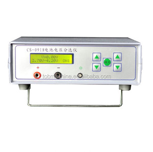
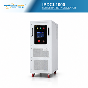
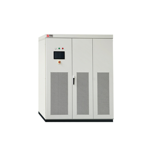
IPDCL1000 Series 220V 1KW High-Precision Battery Simulator
Advanced constant power programmable DC electronic load featuring fast dynamic transient response, ultra-low ripple voltage output, and seamless bi-directional simulation capability.
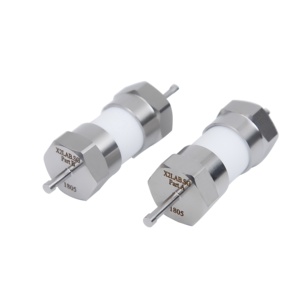
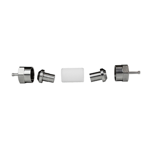
Removable Coin Battery Simulator for Coin Battery Testing
Designed for electrochemical laboratory R&D, delivering high micro-amp resolution transient load steps to accurately emulate coin cell discharge characteristics under pulsed operation.
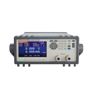
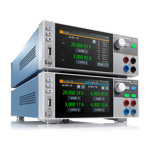
Multi-channel isolated power sink and source system optimized for BMS hardware-in-the-loop (HIL) automated functional validation and high-speed transient pulse evaluation.
Power Aikesaibo High-Dynamic Battery Simulator (150-1000KW)
Megawatt-class heavy-industrial transient electronic load system designed for electric vehicle traction inverter testing, microgrid simulation, and fast regenerative load dissipation.
Industrial-grade dual-quadrant DC power supply and high-speed dynamic transient load, featuring sub-microsecond recovery times and linear regulator precision performance.
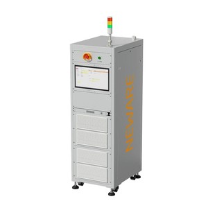
Coin Cell Simulator for CR2032/2016 Electrochemical Testing
Ultra-low noise transient current sink tailored for IoT device energy profiling, electrochemical impedance spectroscopy (EIS), and rapid pulse response logging.
Top 10 Transient Load Factories & Global Exporters Benchmark
An executive engineering report evaluating global power electronics manufacturers, topology efficiency, microsecond dynamic slew rates, and industrial export capabilities.
Understanding Fast Transient Load Testing in Modern Power Conversion
In modern industrial test environments—ranging from electric vehicle (EV) powertrain verification to semiconductor double-pulse characterization—a standard static DC electronic load is insufficient. Transient load testing demands high dynamic slew rates (di/dt up to hundreds of Amperes per microsecond) to simulate real-world disturbances, emergency load shedding, high-frequency pulse-width modulation (PWM) switching, and sudden short-circuit events.
When engineering teams search for the premier transient load factories and exporters, the primary evaluation parameters shift away from simple kilowatt ratings toward internal topology resilience, voltage recovery time, current-fed stability, and parasitic inductance minimization. Global manufacturing leaders differentiate themselves by integrating advanced silicon carbide (SiC) and gallium nitride (GaN) switching circuits, linear MOSFET linear dissipation stages, and DSP-controlled feedback loops that prevent voltage ringing or overshooting during extreme dynamic load steps.
Manufacturer & Origin Tier
Core Power Topology
Transient Slew Rate (di/dt)
Cooling Technology
Primary Industrial Applications
Export & Customization Capability
Magna-Power / USA Tier-1
Current-Fed Switching / Linear MOSFET
Sub-10µs Dynamic Step / 100A/µs
Air & Direct Water-Cooled
EV Powertrain, Wind Tunnels, BMS, Defense
Full Vertical Integration (4-6 Wks Lead)
European High-Precision Hubs
Resonant Converter & Bi-Directional grid
15µs to 25µs Dynamic Slew Rate
Forced Air Cooling
Automotive ATE, Aerospace, PV Inverters
Standard Catalog Models (12-16 Wks Lead)
Asian Industrial Exporters
Traditional Voltage-Fed Switch Mode
50µs to 100µs Response Speed
Air-Cooled Heat Sink Arrays
General Battery Test, Consumer Power Supplies
Mass OEM / High Volume Standard Units
Specialized Lab Instrument Manufacturers
Pure Linear Regulator Architecture
Sub-1µs Ultra-Fast Slew Rate
Convection & Low-Noise Fan
Semiconductor Characterization, Coin Cell R&D
Niche Lab Instruments / Premium Cost
Current-Fed Topology Superiority
Unlike traditional voltage-fed electronic loads that rely on massive parallel capacitor banks on the DC bus, industry-leading transient load factories utilize current-fed power processing. By storing energy inductively rather than capacitively, current-fed loads inherent short-circuit tolerance and zero risk of high-current discharge pulses during initial hookup, protecting delicate devices under test (DUT).
Microsecond Voltage Recovery
When an EV traction inverter shifts from coasting to maximum acceleration, transient load banks must sink current almost instantaneously without allowing the terminal voltage to collapse. Global export leaders design multi-loop control DSP algorithms that achieve transient recovery within 100 microseconds for a 90% load step.
Wide Constant-Power Envelopes
Next-generation electronic loads offer wide operating windows instead of fixed resistance limits. A single 10kW transient load instrument can sinking high current at low voltage (e.g., 500A at 20V) as effectively as high voltage at low current (e.g., 1000V at 10A), eliminating the need to purchase multiple specialized load banks.
2026–2030 Strategic Roadmap
Future Procurement & Technological Trends in Dynamic Load Testing
Key global shifts reshaping dynamic DC electronic load purchasing decisions, high-power density requirements, and automated software integration.
1. Transition to Bi-Directional Regenerative Loads
Procurement teams are rapidly phase-out traditional purely resistive heat-dissipating dynamic loads in favor of 94%+ efficient regenerative power supplies. Modern transient load exporters supply systems capable of acting as both a precise transient power source and a dynamic energy sink, returning absorbed energy directly back to the local AC factory grid to reduce operational HVAC thermal loads and electricity consumption.
As Battery Management Systems (BMS) become more complex, transient testing requires emulating individual lithium-ion cell dynamics during fast pulse charging and balancing. Future procurement prioritizes high-density multi-channel cell simulators (such as 24-channel modules) that offer millivolt accuracy, channel-to-channel isolation (>1000V DC), and microsecond fault-insertion capability.
3. Wide-Bandgap (SiC/GaN) Fast Transient Demands
With silicon carbide (SiC) power switches operating at switching speeds exceeding 100 kHz, dynamic electronic loads must respond without introducing ringing caused by internal lead inductance. Top factories are adopting low-inductance planar bus bars and ultra-fast linear MOSFET stages to match the aggressive di/dt stress testing required by aerospace and EV propulsion engineers.
4. Water-Cooling Integration for High-Density Racks
Air cooling reaches its physical limits in megawatt-class test bays due to acoustic noise and facility airflow constraints. Procurement trends show a 40% annual increase in direct water-cooled transient load configurations (such as 500kW to 10MW systems), enabling 100kW+ power sinking within compact 16U to cabinet form factors.
5. API-First SCPI & Python Automation Software
Modern Automated Test Equipment (ATE) environments demand plug-and-play Ethernet/LXI, Modbus TCP, and USB interfaces. Modern transient load platforms include native NI LabVIEW drivers, IVI compliance, and Python API suites, enabling seamless synchronization between solar array emulation, battery testing, and real-time HIL controllers.
Vertically Integrated Manufacturing
Why Engineering Teams & Global Buyers Standardize on Our Platform
From custom magnetic winding to sheet metal fabrication and 100% full-power burn-in validation under one roof.
Selecting the right transient load exporter requires evaluating long-term manufacturer stability, spare parts availability, and strict manufacturing oversight. Unlike OEM assemblers who outsource sub-components to third-party vendors, vertically integrated power electronics facilities maintain complete design control over every critical sub-system.
In-House Custom Magnetics & SMT Assembly: Precision winding of current-fed inductors and transformers guarantees consistent thermal dissipation and tight inductance tolerances essential for fast microsecond transient steps.
100% Full-Power Burn-In Verification: Every single transient electronic load and battery simulator undergoes comprehensive full-load environmental burn-in before shipping, eliminating early-life component failures.
Unmatched 4 to 6 Week Lead Times: By holding raw material inventory and manufacturing sheet metal, populated PCBs, and heavy assemblies in-house, standard build cycles are reduced from industry averages of 16-24 weeks down to just 4-6 weeks.
Unified Programming Command Architecture: Whether utilizing a 1U 1.5kW benchtop unit or a 3MW water-cooled cabinet, the SCPI command structure, digital interface pinouts, and protection logic remain identical—protecting legacy software investments.
Global Calibration & Service Network: Factory calibration and engineering support centers spanning North America, Europe, Australia, and Asia ensure minimal operational downtime for critical production test lines.
Frequently Asked Questions by Sourcing Teams & Power Engineers
Expert guidance on transient response speeds, voltage overshoot protection, parallel master-slave operation, and custom load profiling.
What defines a "transient load" compared to a standard DC electronic load?
A standard DC electronic load is optimized for steady-state power sinking where current levels change slowly. A transient load features specialized high-bandwidth feedback loops, low internal inductance, and fast power semiconductors capable of stepping current from 10% to 90% load within microseconds (di/dt rates up to 100A/µs). This allows engineers to measure dynamic voltage recovery times, loop stability, and over-current protection mechanisms in power converters and batteries.
How does current-fed topology protect devices under test during rapid transient steps?
Current-fed topology utilizes a heavy series inductor on the DC bus rather than large filter capacitors. During sudden load transients or accidental output short circuits, the inductor naturally limits the rate of current rise (di/dt), preventing massive energy spikes from damaging sensitive devices under test (such as prototype fuel cells or wide-bandgap SiC semiconductors).
Can multiple dynamic load units be paralleled for high-power megawatt testing?
Yes. Through dedicated master/slave high-speed digital interface buses, multiple transient load modules can be connected in parallel to function as a single high-power instrument. The master controller automatically balances current sharing across all slave units with sub-microsecond synchronization, scaling system capacity up to 10 MW without compromising transient response dynamic performance.
What cooling method is recommended for high-duty cycle transient test bays?
For power levels below 100 kW in open laboratory spaces, forced-air cooling is standard. However, for continuous heavy transient testing, enclosed production lines, or systems scaling from 150 kW to multiple megawatts, water-cooled architectures are strongly recommended. Water cooling rejects heat directly to facility chilled water loops, operating completely silently while preventing thermal buildup in high-density rack enclosures.
What are the typical lead times for made-to-order dynamic battery simulators and transient loads?
Due to vertical integration—where magnetic component winding, sheet metal fabrication, SMT board assembly, and final burn-in are executed in a single facility—typical lead times are only 4 to 6 weeks. Selected standard voltage and power configurations are also maintained in ready-to-ship stock for urgent replacement or production expansion requirements.
What software drivers and remote interfaces are supported for automated ATE racks?
All equipment includes standard Ethernet/LXI, USB, RS-232, and isolated 37-pin analog/digital user I/O ports. Optional IEEE-488 (GPIB) and Modbus TCP interfaces are also available. Units support standard SCPI command syntax and ship with native NI LabVIEW drivers, IVI-COM/IVI-C drivers, and documented Python code templates for rapid test automation integration.
Consult with Senior Application Engineers Today
Need tailored voltage/current envelopes, sub-microsecond slew rate confirmation, or custom multi-channel battery simulation? Contact our technical team for immediate spec review and factory quotation.