Custom OEM Active Load Factory & Supplier

Precision Programmable Electronic Loads, Battery Cell Simulators, and High-Dynamic Power Testing Systems for Automotive, Aerospace, and Energy Storage Applications.

Direct Manufacturing Portfolio

Featured Active Load & Battery Simulator Systems

Explore our factory-direct OEM DC electronic loads and precision battery cell simulators engineered for BMS validation, EV power module testing, and high-frequency dynamic load emulation.
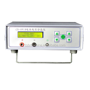
Lithium Ion Battery Voltage Current Capacity Tester

High-precision multi-channel battery capacity and voltage active testing equipment for laboratory cell qualification.
Inquire Now
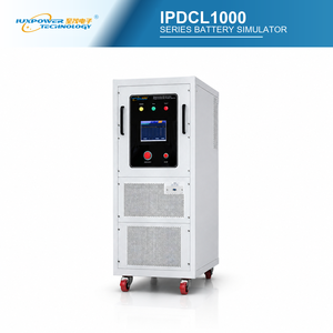
IPDCL1000 Series 220V 1KW High-Precision Battery Simulator

Constant power electronic active load featuring fast transient response and bi-directional simulation logic.
Inquire Now
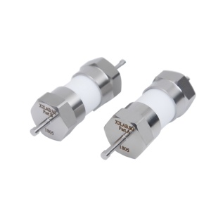
Removable Coin Battery Simulator for Cell Testing

Modular micro-current active load fixture optimized for coin cell micro-power characterization and SOC estimation.
Inquire Now
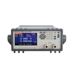
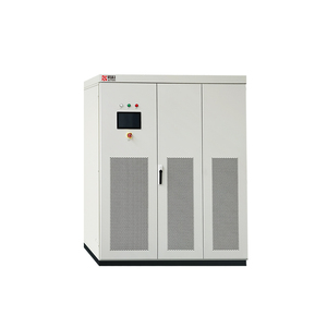
JK5506 Multi-Channel Programmable Battery Simulator

Isolated channel active load array engineered for BMS cell balancing and automated ATE integration systems.
Inquire Now
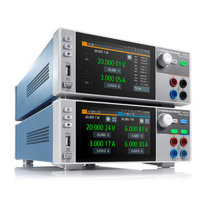
ABS High-Dynamic Battery Simulator 150-1000KW

Megawatt-class liquid-cooled active load system built for heavy industrial EV powertrains and grid energy testing.
Inquire Now
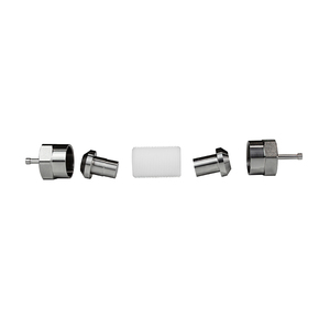
Industrial DC Power Bipolar Active Battery Simulator

Linear MOSFET bipolar DC electronic load providing seamless source-to-sink current control and ultra-low noise.
Inquire Now
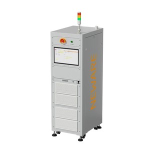
Electrochemical Lab Coin Cell Simulator (CR2032/2016)

Ultra-precise active current sink designed for electrochemistry research, micro-load duty cycles, and sensor validation.
Inquire Now
24-Channel Battery Cell Simulator for BMS Validation

High-density 24-channel hardware-in-the-loop active simulator with programmable SOC, current sinking, and fault simulation.

Inquire Now
40+
Years Power Engineering Heritage
10 MW
Max Paralleled Testing Power
< 10 µs
Fast Dynamic Current Slew Rate
4-6 Wks
Rapid OEM Custom Build Lead Time
Engineering Whitepaper & Technical Insights

Architectural Engineering of High-Performance OEM Active Loads

In modern power electronics test environments, an active load (or programmable DC electronic load) serves as a critical tool for stressing power converters, fuel cell stacks, EV traction batteries, and solar PV strings. Unlike static resistive banks, a true custom OEM active load dynamically regulates input impedance, voltage, current, and total power absorption through precise closed-loop semiconductor control.

As global decarbonization accelerates electrification across automotive, aerospace, and renewable grid infrastructures, the technical requirements placed upon active load suppliers have evolved from basic energy dissipation to high-speed dynamic transient response, bi-directional energy regeneration, and high-density multi-channel cell emulation.

1. Linear MOSFET Topology vs. Switch-Mode PWM Load Architectures

When specifying a custom OEM active load from a manufacturing partner, power design engineers must evaluate two primary internal architectures: Linear Active Loads and Switching (PWM) Active Loads.

  • Linear MOSFET Active Loads: Operate power transistors continuously in their active (saturation) region. This design delivers zero switching noise injection, extremely wide control bandwidth (>100 kHz), and microsecond-level current rise times. It is the gold standard for testing sensitive electrochemical devices, battery cell simulation, low-noise DC-DC converters, and metrology-grade equipment.
  • Switching Active Loads & Regenerative Converters: Utilize high-frequency PWM switch-mode conversion (often utilizing Wide-Bandgap SiC MOSFETs or GaN devices) to convert dissipated DC energy back into AC utility grid power with efficiencies exceeding 95%. While introducing mild switching ripple, regenerative active loads dramatically reduce thermal management footprints and operational utility costs in high-power test bays above 50 kW.
Technical Criterion Linear MOSFET Active Load Switch-Mode / Regenerative Active Load
Dynamic Response (di/dt) Ultra-Fast (< 5 µs to 10 µs) Moderate (100 µs to 1 ms)
Switching Noise & Ripple Zero Switching Noise (< 1 mV RMS) PWM Ripple Present (Filtered via LC)
Power Density & Footprint Standard (Requires large heatsinks) Ultra-High Power Density
Energy Efficiency Thermal Dissipation (100% Heat) 92% – 96% Grid Regenerative
Primary OEM Application BMS Cell Simulation, Metrology, Aerospace EV Powertrain, Pack Cycling, MW Grid Inverters

2. Advanced Operational Modes in Custom OEM Load Engineering

Our OEM factory custom-engineers firmware DSP algorithms to support six distinct active load control modes to replicate complex real-world load behaviors:

  1. Constant Current (CC): Maintains exact current sink despite device-under-test (DUT) voltage fluctuations. Crucial for power supply load regulation verification.
  2. Constant Voltage (CV): Regulates input terminal voltage by sinking whatever current is required. Used for battery charger validation and solar panel MPPT tracking.
  3. Constant Resistance (CR): Emulates precise linear resistance based on Ohm’s Law, ideal for testing startup transient surge currents in electric motors.
  4. Constant Power (CP): Automatically adjusts current inversely with voltage to draw constant wattage, simulating DC-DC converter input stages.
  5. Dynamic Pulse & List Mode: Executes complex step response profiles with programmable slew rates up to 10 A/µs for stress-testing voltage stability.
  6. Electrochemical Impedance Spectroscopy (EIS) Emulation: Superimposes small-signal AC current perturbations over a DC bias load to measure real-time internal resistance in lithium-ion cells.
Strategic Sourcing Analysis

Future Sourcing & Technological Trends in Active Load Procurement (2025–2030)

1. Transition to 1500V High-Voltage Architecture

Driven by 800V automotive EV platforms and 1500V utility-scale solar/storage microgrids, procurement teams are rapidly abandoning legacy 600V load equipment. Future-proof active load procurement focuses on high-isolation design, clearance distance safety, and SiC-based active switches capable of handling continuous 1200V–1500V DC operating windows without thermal derating.

2. Multi-Channel Hardware-in-the-Loop (HIL) Emulation

Modern Battery Management System (BMS) verification requires testing hundreds of series-connected lithium cells under dynamic balance loads. Sourcing trends favor modular 24-channel and 48-channel active cell simulators that provide independent sinking/sourcing, micro-ampere precision current monitoring, and simulated open-circuit fault injection via hardware digital buses.

3. High-Density Liquid Cooling Infrastructure

As test lab space becomes increasingly expensive, air-cooled 100 kW load banks requiring massive thermal exhaust plenum fan noise are being replaced by direct liquid-cooled active loads. Utilizing deionized water-glycol cold plates, modern megawatt active loads fit into compact 19-inch rack enclosures, cutting thermal space requirements by over 70%.

E-E-A-T Enterprise Authority

Why Partnering with Our OEM Active Load Manufacturing Facility Drives Competitive Advantage

As a vertically integrated custom OEM active load factory, we do not simply assemble off-the-shelf components. We manage the entire lifecycle of power instrument creation—from magnetic transformer winding and surface-mount PCB assembly to high-voltage isolation potting, custom chassis sheet metal fabrication, and 100% full-power burn-in validation.

Custom Firmware & Communication Protocols

Every instrument can be pre-configured with SCPI command sets, CANbus 2.0B, Modbus TCP, Ethernet/LXI, or IEEE-488 (GPIB) control interfaces. Native drivers for NI LabVIEW, MATLAB/Simulink, and Python automation environments eliminate software integration friction.

Rugged Current-Fed & Thermal Engineering

Our proprietary power topologies incorporate heavy-duty inductive energy storage and conservative semiconductor derating margins. This structural design grants inherent immunity against DUT short circuits, dynamic inductive load spikes, and arc discharge overvoltages.

Vertically Integrated Manufacturing Agility

By executing metal enclosure fabrication, planar magnetics fabrication, and automated optical SMT assembly under one roof, we reduce typical industry custom prototype lead times from 20 weeks down to just 4 to 6 weeks.

Procurement & Engineering FAQ

Frequently Asked Questions by OEM Procurement Teams

What is the difference between an active load and a passive resistive load?
A passive resistive load consists of static fixed resistor elements where current draw is purely proportional to applied voltage ($I=V/R$). An active load utilizes semiconductor power devices (MOSFETs or IGBTs) governed by high-speed analog control loops or digital signal processors (DSPs). This enables the active load to maintain precise constant current, constant voltage, constant power, or dynamic step-ramp profiles regardless of how the source voltage under test fluctuates. Active loads are mandatory for qualifying modern closed-loop power supplies, batteries, and fuel cells.
Can your custom active loads support bi-directional power flow and battery emulation?
Yes. Our high-dynamic battery simulator series (such as the IPDCL1000 and ABS series) feature dual-quadrant bi-directional active switching circuits. They seamlessly transition between sinking current (acting as an active load during battery charging simulation) and sourcing current (acting as a programmable DC supply during battery discharging simulation) in under 1 millisecond without voltage overshoot or output glitching.
How does your OEM facility ensure product quality and long-term reliability?
Every active load system manufactured in our factory undergoes rigorous Quality Assurance protocols, including ISO 9001 quality system adherence, automated optical inspection (AOI) of SMT boards, high-voltage dielectric withstand (Hi-Pot) safety testing, and 100% full-power thermal burn-in under elevated ambient conditions for 48 hours prior to factory shipment. Detailed calibration certificates traceable to international standards (NIST/ISO 17025) are included with each unit.
What liquid cooling parameters are required for high-power active load cabinets?
Our water-cooled active load systems (ranging from 20 kW to 10 MW) utilize industrial stainless steel or copper cooling plates designed for standard industrial water-glycol mixtures (up to 30% Ethylene Glycol). Recommended coolant inlet temperatures range from +15°C to +30°C at operating pressures up to 6 bar. Built-in flow sensors, leak detection interlocks, and condensation preventers ensure maintenance-free operation in cleanroom or laboratory environments.
Can multiple active load units be paralleled for higher power requirements?
Absolute performance scaling is achieved through our master-slave digital bus control architecture. Up to 64 individual active load modules or rack systems can be connected in parallel. The master unit automatically redistributes programmed load currents equally across all slave units, presenting a single SCPI command interface to the user's automated ATE software test environment.
What options are available for low-voltage, high-current micro-resistance testing?
Testing single cell batteries, fuel cell stacks, or low-voltage DC busbars requires an active load capable of sinking full rated current at input voltages as low as 0.2V to 0.6V (to compensate for wire voltage drop). We offer specialized Low-Voltage High-Current (LVHC) linear active load options integrated with remote sense lines to guarantee full current capability down to near-zero volt conditions.
What is the typical lead time for custom OEM active load designs?
Because we maintain vertical manufacturing control over sheet metal machining, magnetic coil winding, and PCB population, standard customized OEM variations take 4 to 6 weeks. High-volume standardized rack-mount units and cell simulators are frequently stocked in ready-to-ship inventory for expedited 7-day dispatch.

Consult with Our Senior Active Load Applications Engineers

Require a custom voltage range, specialized dynamic pulse rates, or a multi-channel BMS battery cell simulator tailored to your exact ATE system specifications? Contact our factory engineering team today for custom technical proposals, CAD drawings, and factory direct quotes.