
Explore high-performance pulse load testing equipment, multichannel cell simulators, and programmable bipolar power supplies verified for industrial laboratory reliability.
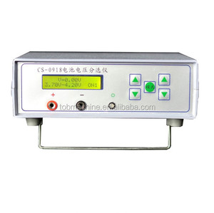
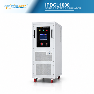
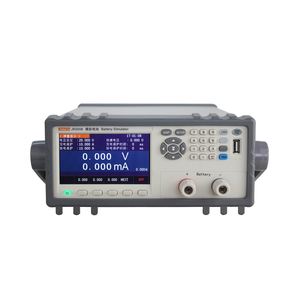
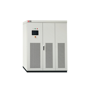
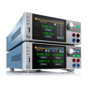
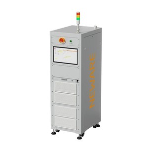
In the contemporary electrical engineering and energy storage landscape, validating energy storage systems, traction inverters, and power semiconductors under transient dynamics requires instrumentation far beyond static DC power supplies. Dynamic pulse testers and high-speed battery simulators form the empirical bedrock for assessing equivalent series resistance (ESR), dynamic internal impedance, pulse discharge capability, state-of-charge (SOC) tracking algorithms, and switching losses in wide-bandgap (SiC/GaN) devices.
Purchasing CE-certified pulse testing instruments ensures compliance with European conformity standards—specifically low-voltage directives (LVD IEC/EN 61010-1) and electromagnetic compatibility requirements (EMC IEC/EN 61000-6-2 / 61000-6-4). For engineering managers, global procurement leads, and system integrators, selecting qualified manufacturers who integrate low-inductance switching topologies, fast slew-rate control, current-fed isolation, and continuous full-power burn-in procedures is critical to mitigating operational risk and securing measurement repeatability.
Traditional voltage-fed switch-mode power supplies rely heavily on large capacitive output banks. Under high-frequency pulse load conditions or rapid short-circuit transients, these capacitors discharge abruptly, leading to severe ringing, overshoot, or destructive over-current spikes. Advanced pulse testers utilize current-fed topologies featuring energy-storing series inductors. This current-fed architecture inherently limits dynamic fault currents, providing immune short-circuit operation, graceful behavior into dynamic reactive loads, and superior lifespan under repetitive multi-kilohertz pulse profiles.
A primary failure mode in long-term high-power pulse testing equipment stems from sub-tier component sourcing and unverified third-party assemblies. Superior factory capability relies on vertical integration, where critical magnetics winding, sheet metal fabrication, printed circuit board (PCB) assembly, surface-mount technology (SMT), thermal heat-sink machining, and final full-power burn-in occur under a unified quality management system (ISO 9001 certified).
Custom-wound transformers and high-frequency chokes engineered specifically for high pulse-current di/dt rates, minimizing skin-effect losses and thermal saturation under high duty-cycle testing.
Every industrial pulse tester and cell simulator undergoes 100% full-power thermal stress burn-in and automated automated calibration before factory dispatch, guaranteeing out-of-the-box MTBF benchmarks.
Combining fast FPGA digital signal processors (DSP) with linear MOSFET sinking stages to eliminate switching noise injection when characterizing ultra-sensitive battery cells and low-noise fuel cell stacks.
From micro-amp level coin cell simulators (CR2032/CR2016 electrochemical characterization) up to megawatt-scale (150kW – 10MW) battery pack emulators, industrial manufacturers must ensure uniform command sets (SCPI standard), consistent analog/digital I/O pinouts, and seamless integration with hardware-in-the-loop (HIL) automation platforms such as NI LabVIEW, MATLAB/Simulink, Python SDKs, and RESTful API endpoints over LXI-certified Ethernet.
CE-certified pulse testers and battery simulators fulfill distinct technical roles across modern R&D and production testing facilities. Below is an engineering overview of key operational domains:
The table below summarizes standard industrial parameters expected when sourcing high-tier CE certified pulse testers and battery simulator systems from top-tier suppliers:
| Equipment Platform | Power Range | Voltage & Current Range | Dynamic Transient Response | Primary Application Target |
|---|---|---|---|---|
| Low-Power Cell Simulator | 1W – 50W / channel | 0 – 6V DC | 0 – 5A / channel | < 10 μs step response | BMS Validation, SOC Estimation, Passive Balancing |
| Benchtop Dynamic Pulse Tester | 1 kW – 10 kW | 0 – 600V DC | 0 – 300A Pulse | < 50 μs (0 to 90% load) | Module Level ESR, Pulse Discharge, IoT Duty-Cycles |
| Linear MOSFET DC Load / Tester | 1.25 kW – 20 kW+ | 0 – 1000V DC | 0 – 1200A Sinking | Ultra-low noise, 0 switching ripple | Fuel Cell Characterization, Converter Load Transient |
| High-Power Pack Simulator | 150 kW – 10 MW | 100V – 1500V DC | up to 4000A | < 1 ms dynamic reversal | EV Powertrain HIL, Microgrid Energy Storage Testing |
| Bipolar High-Precision Simulator | 100W – 3 kW | -30V to +30V | Bipolar 2-Quadrant | < 20 μs recovery time | RF PA Pulsed Testing, Semiconductor Reliability |
Global procurement teams navigating the transition to high-voltage architectures (800V/1200V EV platforms, 1500V grid-scale storage) face shifting technological and logistical benchmarks. Industry data highlights four key procurement trends shaping factory equipment specifications over the coming decade:
Legacy pulse testing facilities dissipated absorbed energy as waste heat through resistive bank arrays, demanding immense HVAC cooling capacity and increasing carbon footprints. Modern factory sourcing guidelines prioritize bi-directional regenerative simulators capable of returning >94% of absorbed electrical energy back to the AC grid. This transition yields double-digit reductions in total cost of ownership (TCO) and operating expenditure (OPEX).
As SiC and GaN power switches elevate inverter operating frequencies into the hundreds of kilohertz, legacy pulse testers with microsecond-range slew rates introduce measurement lag and distortion. Forward-looking procurement specifications demand programmable current slew rates exceeding 100 A/μs and integrated high-speed digitizers sampling at 1 MS/s to 10 MS/s. This allows simultaneous pulse simulation and high-resolution transient waveform capture without requiring outboard oscilloscope setups.
Test bays require flexibility to reconfigure assets between low-voltage battery module testing and high-voltage megawatt-class powertrain validation. Sourcing managers increasingly favor modular rack-mount designs (1U to 3U form factors) equipped with digital bus interfaces (e.g., MagnaLINK™ distributed DSP protocols). These systems enable multiple physical power supplies to behave automatically as a single unified master-slave instrument without control latency or cross-unit current imbalance.
Unplanned downtime in automotive or aerospace production lines costs thousands of dollars per hour. Next-generation pulse testers feature embedded edge analytics that monitor thermal drift, capacitor equivalent series resistance degradation, fan speed harmonics, and IGBT health metrics in real time. Automated alert systems notify maintenance teams prior to calibration standard out-of-tolerance events, ensuring continuous compliance with IATF 16949 automotive quality directives.
Technological advancement in dynamic power testing is accelerating across three distinct vectors: control loop bandwidth, thermal management efficiency, and software emulation fidelity.
Utilizing high-density Field Programmable Gate Arrays (FPGAs) running deterministic closed-loop algorithms allows pulse testers to adjust voltage/current output within sub-microsecond timeframes, eliminating ringing on complex non-linear loads.
For high-power cabinet systems (500 kW to 10 MW), closed-loop water cooling eliminates internal dust accumulation, reduces laboratory acoustic noise below 65 dBA, and shrinks instrument footprint by up to 60% compared to air-cooled equivalents.
Sophisticated mathematical software packages (such as Photovoltaic & Battery Emulation suites) dynamically map internal resistance ($R_i$), open-circuit voltage ($V_{oc}$), thermal coefficients, and aging curves for NMC, LFP, LTO, and Solid-State chemistries in real time.
Furthermore, ultra-low drift precision metrology attachments (such as high-stability sensing modules) achieve current stability under 10 ppm/°C, unlocking atomic-scale precision for particle accelerator magnet power supplies, superconducting coil testing, and electrochemical deposition monitoring.
When selecting a factory supplier for CE-certified pulse testers, assessing the supplier's engineering heritage and manufacturing integrity is paramount. Leading manufacturing facilities leverage over four decades of dedicated power electronics design, controlling every step of the supply chain from raw sheet metal to final firmware releases.
By housing engineering desks adjacent to the manufacturing floor, the feedback loop between field performance data and design enhancements is drastically shortened. Key factory qualifications to verify during OEM/ODM audits include:
Critical questions asked by test engineers, quality assurance managers, and international buyers during pulse tester procurement.
CE certification for pulse testers requires compliance with two primary European directives: the Low Voltage Directive (LVD 2014/35/EU) using harmonized standard EN 61010-1 (Safety requirements for electrical equipment for measurement, control, and laboratory use), and the EMC Directive (2014/30/EU) under EN 61000-6-2 (Immunity for industrial environments) and EN 61000-6-4 (Emissions for industrial environments). Always request official Declaration of Conformity (DoC) documents and test reports from your equipment supplier.
Steady-state DC testing evaluates continuous power delivery under static voltage or current conditions. In contrast, dynamic pulse testing subjects the Device Under Test (DUT) to rapid, high-frequency current steps (microsecond rise times) to simulate real-world transient conditions—such as electric vehicle fast acceleration spikes, battery internal resistance (ESR) voltage drops, or pulsed radar emissions. Pulse testing reveals thermal stress, inductive voltage spikes, and control loop stability issues that static testing cannot detect.
Current-fed topologies store energy in a series inductor rather than a large output capacitor bank. This design provides natural immunity to load short-circuits and arcing, eliminates massive capacitive discharge surges during fast transients, offers superior stability into inductive or reactive loads, and dramatically enhances long-term reliability under repetitive high di/dt stress.
While software control interfaces remain identical across equipment families, physical hardware is optimized for specific operating ranges. Coin cell testing requires multi-channel low-power simulators with micro-amp current measurement resolution and ultra-low noise linear output stages. Conversely, EV battery pack simulation requires high-voltage (up to 1500V) bipolar switch-mode or regenerative cabinet systems capable of handling hundreds of kilowatts. Utilizing unified platform architectures from a single manufacturer allows engineers to share test scripts and automation drivers seamlessly across both scale extremes.
A multi-channel battery cell simulator provides independently isolated DC output channels that act as individual lithium-ion battery cells connected in series. It allows test engineers to simulate individual cell over-voltage, under-voltage, state-of-charge imbalance, open-wire faults, and temperature sensor failures in a safe, repeatable HIL environment. This validates BMS safety trip logic and active/passive balancing algorithms without risking cell degradation or fire hazards.
Industrial-grade pulse testers come standard with isolated Ethernet/LXI, USB, and RS-232 interfaces, alongside isolated 0-10V analog/digital I/O ports. Optional interfaces include IEEE-488 GPIB and Modbus TCP. Software support includes standard SCPI command sets, IVI drivers, Native NI LabVIEW virtual instruments, MATLAB toolboxes, and open-source Python libraries for automated test equipment (ATE) rack integration.
Vertically integrated factories that machine sheet metal, wind magnetics, and assemble PCBs in-house typically maintain standard lead times of 4 to 6 weeks for custom-configured power systems, with common stock units available for immediate dispatch. Available factory options include integrated reverse-blocking diodes, ultra-fast slew rate output modifications, water cooling packages, high-stability DBx metrology units, and custom input AC line voltage configurations (e.g., 208VAC to 480VAC 3-phase).
Reputable suppliers provide standard 2-year or 3-year factory warranties supported by global service hubs across North America, Europe, the UK, Australia, and Asia-Pacific. Calibration can be verified on-site using standard automated calibration routines and NIST-traceable digital multimeters, or performed at local certified regional service depots to minimize equipment downtime.
Need precise advice on voltage slew rates, dynamic response specs, channel isolation, or CE compliance documentation for your test bay? Connect directly with our engineering team today.
Get a Quote