Choosing a supply for wide-bandgap testing is not a simple voltage-and-current exercise. SiC and GaN devices switch quickly, expose measurement weaknesses, and can behave differently under realistic loads. A supply that looks adequate on a datasheet may still produce unstable transitions, excessive ripple, or misleading results on the bench.
A sound selection starts with the device’s operating range, then checks voltage and current headroom, transient response, output noise, and protection behavior. Consider how the setup will capture startup, switching, and fault conditions. Pay attention to cable length, grounding, and the load’s thermal state; each can change what your instruments report. Small details matter. So does repeatability. For SiC and GaN Testing Power Supplies, the goal is not simply to deliver power, but to create controlled, measurable conditions without masking the device’s real behavior.
Dr. Alex Lidow is a recognized GaN industry expert. I cannot verify a verbatim quotation from the material provided, so the following is an editorial principle, not a direct quote: “Choose test power around the device’s real operating stresses, not just its headline ratings.” That distinction guides this article’s comparison of supply capabilities and test requirements. It also leaves room for a practical caveat: no single specification predicts every bench result. Engineers should validate the chosen supply with their actual device, fixture, and measurement setup before trusting the data.
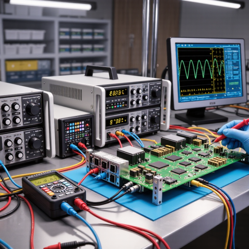
A 650 V GaN device and a 1,200 V SiC device belong to different voltage classes, but those labels are not test settings. Check the device datasheet and test method before choosing a supply. The required output depends on the planned operating point, switching conditions, and safety margin. Do not assume a higher-rated device always needs a supply set to its full rating.
For 650 V GaN testing, verify that the supply can provide the required bus voltage with stable regulation and controlled transients. Fast switching can make overshoot and ringing important, even when the average voltage looks correct. For 1,200 V SiC devices, confirm the supply’s voltage range, insulation, and measurement setup are suitable for the intended test. Keep probes, cables, and fixtures within their specified ratings. Details matter.
Current capability also matters. A supply that reaches the target voltage may still struggle during startup or load changes. Check output power, current limits, protection behavior, and recovery after a fault. In practice, the fixture can influence results more than expected; I have seen setup details get less attention than the DUT rating. Record the actual test conditions, including voltage, current, and temperature, so later measurements remain comparable.
For SiC and GaN testing, match the supply’s voltage range and output power to the device’s operating point. Use P = V × I. A 400 V DC bus drawing 5 A requires 2 kW. At 800 V, the same 5 A requires 4 kW. That doubled demand is easy to miss when voltage gets most of the attention. Keep the bus within the supply’s rated limits, including expected voltage transients.
Tips: Calculate power at the maximum planned current, not just the nominal value. Allow headroom for startup and transient loads, then verify the supply’s continuous rating and cooling needs. A 10% margin on 4 kW gives 4.4 kW. Treat this as a planning example, not a universal rule.
Check how well the supply regulates at low current and responds to changing loads. Confirm that cables, connectors, and protection devices can handle the intended voltage and current. Long cables can introduce voltage drop, so measure at the test point when practical. A power calculation is useful, but it cannot capture every test condition. Revisit the estimate after checking the actual load profile.
Size output power with P = V × I for 400 V and 800 V DC buses.
These values are calculated from bus voltage multiplied by current: for example, 400 V × 25 A = 10 kW. They represent ideal DC output power and do not include conversion losses or design margin. Select a supply with suitable voltage, current, and power capability for the intended test conditions.
For switching tests, size the supply around the test bus and pulse current, not the device’s headline rating. A 650 V GaN device may be tested on a 400 V bus; a 1,200 V SiC device needs a different voltage range and suitable safety margin. Yole Group’s 2023 Power SiC report estimated the market at about $2.3 billion in 2022, with growth to roughly $9.2 billion by 2028. That expanding range of devices makes one fixed test setup less useful. Keep voltage accuracy and current headroom in view. A supply that reaches the set voltage slowly can distort the starting condition.
Transient response matters just as much. Check recovery after a load step, voltage overshoot, and settling time at the DUT terminals—not only at the supply output. Fast switching edges expose stray inductance in leads and bus connections. Keep the supply loop short, and verify the waveform with a differential probe. Small details matter. During double-pulse testing, confirm that the supply can support the chosen pulse current without triggering current limit or foldback. JEDEC’s power-device characterization guidance emphasizes controlled, repeatable test conditions; record bus voltage, current, temperature, and wiring layout with every result. A specification sheet rarely tells the whole story. The easy-to-miss part is that “fast response” depends on the load and cabling, so validate it on the assembled bench.
When testing SiC and GaN devices, decide whether your supply must only deliver power or also absorb it. A bidirectional supply can sink current during turn-off, reverse-conduction, and load-pull tests. Without sinking capability, energy returned by the device may raise the output voltage or require an external load. That means more heat, extra wiring, and another variable to check.
Yole Intelligence’s 2023 Power SiC report forecast the SiC power-device market would grow from about $2.3 billion in 2023 to $9.2 billion by 2028. That growth makes repeatable, high-throughput testing increasingly important.
For longer test runs, regenerative supplies can return absorbed energy to the facility rather than dissipating it as heat. Check the voltage and current limits in both directions, not just the source rating. Also verify transient response: a fast SiC switch can return energy before a slow control loop reacts.
Look for clear sink-mode specifications and safe behavior when the test stops. Small detail. A bench can appear efficient on paper and still waste energy through conversion losses.
I would compare measured wall-plug power under the actual test profile; datasheet efficiency alone does not tell the whole story.
When selecting a power supply for SiC or GaN testing, treat IEC 61010-1 as a safety baseline, not a performance rating. The standard addresses hazards in measurement, control, and laboratory equipment; it does not prove a setup is safe in every configuration. Check the documentation.
Review rated working voltage, insulation category, and protective-earth instructions against the test fixture and intended environment. For high-voltage bias, confirm isolation ratings and required creepage and clearance distances. A small PCB gap can matter when dust or humidity is present. Do not rely on the supply’s front-panel voltage limit alone.
Fast-switching devices can produce sharp transients, while output capacitors may retain charge after shutdown. Choose supplies with documented overvoltage, overcurrent, and thermal protection, then verify their behavior under relevant fault conditions. Look for safe discharge provisions, interlocks, and clear status indication. Test carefully. A protective feature may trip too slowly for a particular fixture or interact with external clamps. That detail is easy to miss. Record wiring, grounding, and discharge checks, and inspect cables and connectors for heat or damage during repeated runs. Compliance markings help, but installation and maintenance still shape the actual risk.
| How to Choose Power Supplies for SiC and GaN Testing – Check Electrical Safety and Protection Against IEC 61010-1 | ||
|---|---|---|
| Selection Area | What to Check | Practical Guidance and Evidence |
| Test voltage and device class | Required bus voltage, test waveform, device voltage rating, and planned operating margin. | Choose an output range that covers the test procedure and its specified margin. Common SiC device voltage classes include 650 V, 1,200 V, and 1,700 V; these are device ratings, not recommended test voltages. Set test limits from the device datasheet and approved procedure. |
| Output current and power | Steady-state current, pulsed current, load profile, and supply power limit. | Calculate voltage × current for the expected operating point, then check the supply’s continuous and transient ratings. Confirm whether the supply can handle the test duration and load changes without entering current limit or thermal shutdown. |
| Voltage regulation and ripple | Output accuracy, ripple, noise, and measurement bandwidth. | Set limits based on the test’s uncertainty budget and DUT requirements. Compare specifications using the same bandwidth and measurement conditions; switching ripple and fast transients can require separate measurement methods. |
| Transient response | Overshoot, undershoot, settling time, and behavior during load steps or switching events. | Review transient specifications and verify performance with the intended cabling, load, and probe setup. A supply’s control-loop response may not capture very fast switching-edge behavior, which should be evaluated with suitable test equipment. |
| Output isolation and grounding | Maximum output-to-earth voltage, isolation rating, insulation system, and permitted grounding arrangement. | Check the manufacturer’s documented ratings and operating instructions. Confirm that the planned DUT, oscilloscope, fixtures, and protective earth connections do not unintentionally defeat isolation or create hazardous common-mode voltages. |
| Overvoltage protection | Adjustable overvoltage protection (OVP), trip behavior, and stored output energy. | Set the protection threshold above the required test voltage but below the DUT or fixture’s safe limit, as appropriate. Confirm whether the supply shuts down, clamps, or latches after a trip, and account for energy stored in output capacitors and cables. |
| Overcurrent protection | Current limit, short-circuit response, and recovery behavior. | Choose a current limit that supports the planned test without exceeding DUT, wiring, connector, or fixture ratings. Check the response under the expected load and determine whether automatic retry could create repeated stress. |
| Discharge and stored energy | Output discharge time, residual voltage, and safe access after shutdown. | Verify how the output is discharged and how residual voltage is indicated. Where hazardous energy can remain, use an appropriate discharge and verification procedure before touching the DUT or fixture. |
| Interlocks and emergency shutdown | Remote inhibit, enclosure or fixture interlocks, and accessible emergency disconnect. | For hazardous-voltage test setups, evaluate whether interlocks and shutdown controls are needed by the risk assessment and local rules. Test their operation with the complete system, not only the supply in isolation. |
| Leads, connectors, and fixtures | Voltage and current ratings, insulation condition, creepage and clearance, and strain relief. | Ensure every component in the output path is suitable for the maximum working voltage, expected transients, environment, and current. Keep conductive parts guarded where necessary, and inspect leads and connectors for damage before testing. |
| IEC 61010-1 safety assessment | Equipment category, intended use, accessible parts, protective measures, and applicable edition or national adoption. | IEC 61010-1 is a safety standard for measurement, control, and laboratory equipment; it does not prescribe one universal power-supply voltage, ripple, or protection setting for SiC or GaN testing. Verify the equipment’s conformity documentation and assess the complete test system for its actual installation and use conditions. |
| Operating environment | Ambient temperature, ventilation, humidity, altitude, and contamination conditions. | Check the equipment’s rated operating limits and derating information. Maintain required airflow and keep the setup within its specified environmental conditions; these factors can affect output capability and insulation performance. |
| Engineering note | Test values and safety limits are application-specific. | Treat the guidance in this table as a selection checklist, not as a substitute for the applicable standard, product documentation, device datasheets, or a documented risk assessment. |
It can absorb current returned during turn-off, reverse-conduction, or load-pull tests. Without it, output voltage may rise or an external load may be needed. Extra heat, wiring, and variables follow.
It can return energy to the facility instead of dissipating it as heat. Measure wall-plug power during your actual test profile. Datasheet efficiency alone may not tell the whole story.
Check voltage and current limits in both directions, not only the source rating. I used to focus on source ratings. That was incomplete.
A fast switch may return energy before a slow control loop reacts. Check sink-mode specifications and what happens when testing stops. Small detail.
It provides a safety baseline for laboratory and measurement equipment, not a performance rating. Compliance alone does not prove every setup is safe. Check the documentation.
Compare working voltage, insulation category, and protective-earth instructions with your fixture. Confirm isolation ratings and creepage and clearance distances. Dust or humidity can make a small PCB gap matter.
Check documented overvoltage, overcurrent, and thermal protection. Also review interlocks, status indicators, and safe discharge provisions. Verify behavior under relevant fault conditions.
Record wiring, grounding, and discharge checks. Inspect cables and connectors for heat or damage. A protective feature may respond too slowly or interact with external clamps.
Choosing SiC and GaN Testing Power Supplies starts with identifying the device class and its maximum operating voltage. A 650 V GaN device and a 1,200 V SiC device can require different test ranges and safety margins. Next, estimate the power needed for the test by multiplying voltage by current. For example, testing devices on 400 V and 800 V DC buses calls for checking that the supply can deliver the required current without exceeding its power rating.
Voltage and current limits are only part of the selection. Switching tests may require fast, stable transient response to reproduce changing operating conditions accurately. If tests involve energy flowing back from the device or load, choose a supply with suitable sinking or regenerative capability. Finally, review electrical safety features, including overvoltage, overcurrent, and overtemperature protection, and confirm that the equipment is appropriate for the applicable IEC 61010-1 safety requirements. These considerations help create a test setup that is capable, controlled, and suited to the device under evaluation.